|
level
of difficulty |
beginner
|
intermediate |
advanced |
Build your own sextant
|
Note: Since I published this text, I've done another, much easier sextant using a CD and its box. Click the banner to the righ to visit it. But the octant described in this text is better ;-) |
 |
From times to times I get tired of writing abstract computer programs. This time I decided to do a more concrete project: a sextant (actually, an octant). I'm not a very experienced craftsman and don't have a equipped shop. The design is simple and can be reproduced with hand tools. I used a small jigsaw and a belt sander. I have made no blue prints.
In tests, when compared to a Kern theodolite this octant did agree within 6' (see test results in the bottom of this page). Also tested a Davis plastic sextant.
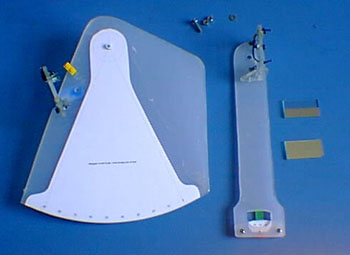 My octant parts ... |
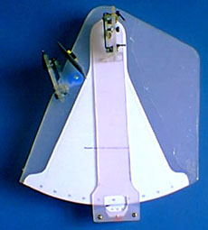 .. assembled |
Printing the Scale
The scale is probably the most difficult sextant component to do using traditional techniques. It must be very precise and allow reading degrees and minutes, with accuracy at least within 5' of arc.
Fortunately, most of us have a precise printing equipment right on our
desktop: a inkjet or laser printer. These machines can print 300 dots
per inch (1200 for laser), with enough precision to print a good sextant
scale.
 |
Sextant scale printer program I wrote a scale printing program. This will print the sextant scale using vector rendering, for best resolution. The scale will be the larger possible in the current printer page size. To the left, you see a screenshot of the XtantScalePrinter
program. I used the default options in my project, but you may experiment
with other designs (3 sextant types, ticks per degree etc.).
|
|
The Vernier scale Since I didn't have the sophisticated machining equipment required, I discarded the idea of a drum sextant and went on to build a vernier scale sextant. Vernier sextants appeared before the modern drum sextants. In the vernier scale sextant, each degree in the scale is divided in 3 ticks (20' wide). |
|
 |
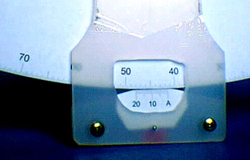
The vernier scale precision can be as good as a drum scale. The only difference is that the vernier scale requires a much more delicate handling of the sextant arm while trimming. Reading the vernier scale is simple once you get used to it. Look at the image to the left. The tick A points to 76° and something. Since, in this sextant, the degree is divided in 3 parts (20' each), we can see that the reading is in the 20' to 40' range. In the vernier scale (the one from A to 20') we can see that the 6th vernier tick coincides with the arc scale tick (give it or take). So the reading is 76°20'+6', or 76°26'. |
Below are the three basic X-tant types. The octant can measure up to 90°, the sextant up to 120° and the quadrant up to 180° (see below). I choose to build an Octant, since this design fits better in a A4 printer page, giving the largest possible degree size in the scale, for best detail. And the 90° scale is enough for most observations.

X-tant types
I used A4 ink jet sticker paper to print the scale (the ones used for printing labels). Choose a paper with no cuts. After printing the scale, check how good is your printer, using a compass to see if the index is a perfect circle segment.
|
Scale Transfer -
An alternative way to print the scale was suggested by Mr. Schmit,
by email: While this reversed print is not directly supported by the scale printer program, most printer drivers (e.g.: HP) offer this as an option. Open the "Printer Setup" dialog, click "Properties" and check the "reverse horizontally" checkbox. Another way was suggested by Mr. Kunnar: " I used inkjet iron transfer paper. It is a kind of plastic that can be transfered to clothes using a hot iron. Since the ink ends up trapped between the sextant frame and the plastic layer, this scale is water proof".
|
Instrument frame
I used a 3 mm tick acrylic board for the instrument frame. This material is easy to machine and is relatively rigid. Acrylic boards are usually sold in large sizes, so you might want to search for someone who works with this material, in order to get the small piece you need with minimum expense.
The size of the sextant will depend on the printed scale size (that´s why there is no blue print). So, you will only "design" the instrument after you have stick the scale on the acrylic board.
The acrylic board comes with plastic layers in both sides, for protection. It's a good idea to keep this protection as long as possible, because the acrylic will be easily scratched. I carefully lifted the plastic protection (see below), stuck the scale and put the plastic back in place, so the sextant scale was also protected while machining the frame.
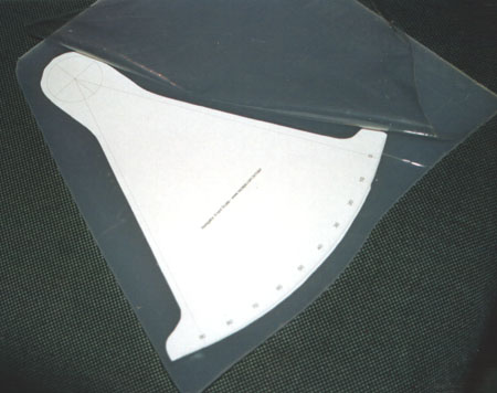
Lift the plastic protection, stick the scale, and put the protection
back in place
After printing, cut around the scale, leaving like 3 mm around the outside line.
Sticking the printed scale in the board is a critical operation. It must be perfectly stuck, free of air bubbles or ripples. Otherwise the scale will not be correct.
Remove from the sticker paper backing completely. Hold it with the two hands and gently place in the acrylic board, the arm axis circle first. Then use one hand to spread the scale, while holding the other side. Keep the paper slightly tensioned, but not so much as to distort it. If you make a mistake, you probably will have to print another scale and start again.
 Frame, arm and vernier, with cut lines |
After this, you can use a marker pen to draw the parts (frame, arm and vernier). The arm window (where the scale is read) must be sized and positioned so that you can see both the scale and the vernier touch point (that will define the arm radius). My octant arm is about 40 mm wide. When designing the arm, measure the scale radius and add 10mm on either side (towards and away from the arm axis). My arm window is 30 mm wide. The image to the left shows the 3 frame parts, marked and ready to be cut.
|
I cut the parts with an electric jigsaw, with thin teeth blade. Take care when cutting along the scale ticks. Never cut across the scale line. If you are careful, you can cut as close as 0.5 mm from the scale. Then you will have little trouble sanding out the rest, until you precisely reach the fine scale line. Use fine sanding paper for finishing the scale arc.
Also carefully cut and sand the vernier contact point, testing frequently against the scale arc. The vernier and scale contact must be as close as possible.
|
|
To drill the arm axis hole, first mark it with a hard point. Drill a 2mm lead hole and then a 7 mm hole. Use sharp drills. Do the same in the frame and make sure the hole center is precisely positioned. I inserted a 7 mm hard plastic tube in the axis, so there is no contact between the arm and screw as the arm is moved (only between the tube and arm). Bond the tube to the frame. The axis screw goes in the middle, with twin nuts. Make sure there is no slack in the arm axis setup After cutting, drilling and sanding, you can assemble the arm
and frame for the fist time. Then you can position and bond the
vernier in the arm, using a couple small drops of loctite (Cyanoacrylate
glue). Use small self tap screws to secure the vernier. |
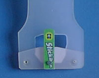 |
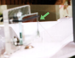
If you did these steps right, the vernier should be in smooth, close contact with the index, as you slide the arm along the arc. Add a plastic device in the back of the arm to press it against the frame (the green part on the left image). It is important to have some friction between the arm and frame, so the instrument will hold the reading if left alone (i.e. the arm will not move by itself). This is also important for fine trimming.
|
Mirrors
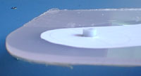
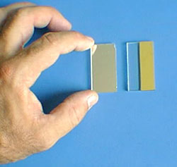
I used 2 equally sized glass mirrors (46 mm x 24 mm, 3 mm tick). Any glass shop will cut these for you. As you know, one of the mirrors must be half silvered. So you must remove half of the mirror silver backing. I used a paper cutter blade for this job (Olfa cutter).
First make a sharp longitudinal cut along the middle of the mirror. Then scratch half of the epoxy protective layer from the back of the mirror, with the blade inclined. The epoxy backing is a hard material, but will come out with patience. Don't use any abrasive material or the blade point, to avoid scratching the glass. Once the epoxy is gone, the silver is easy to remove, rubbing hard with a wet cloth. In the end, the glass must be clear and scratch free (fig. below).
Mirrors
|
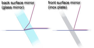
Note: You may be tempted at this point to use a thinner mirror and eliminate the transparent part altogether. Don´t do that. This would introduce a refraction error. The direct (horizon) light ray must pass thru the glass, as the light ray from the star does. This can only be done if you use a front mirrored surface, such as a polished inox plate. |
 |
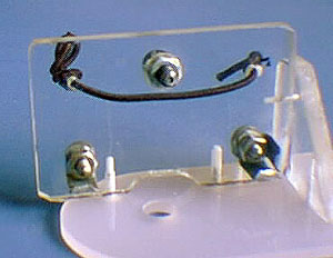
Mirror holders
I used a thicker acrylic for the mirror holders (4mm), as these parts are sometimes subjected to abuse. They will also have to be fixed with self tap screws so a thicker material is better.
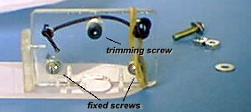
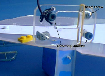
Both mirrors must be supported by three contact points (from geometry, we know that 3 points are required to define a plane). I used 3 supporting screws to position each mirror. Some of the screws are adjustable, for mirror trimming, and some are fixed. For the adjustable screws, I used Allen screws, which have a large head, easy to turn by hand. The fixed points are regular inox nut screws.
|
Make a point in all screw tips, to reduce the contact area between mirror and screw to a point. I also added thin metal plates to prevent the mirrors from moving sideways while trimming. To ensure a perfect contact between the 3 screws and mirror, I used rubber bands (see right). These press the mirrors against the screws. Commercial sextants use metal springs for this function, but I could not find any suitable part in my junk collection. |
 |
|
|
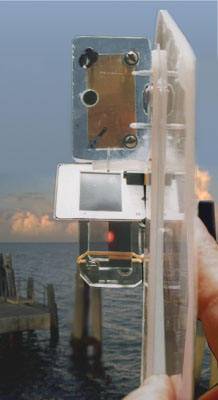
 backview |
|
 |
The arm mirror holder is basically a rectangle, with a side supporting plate. The arm mirror has one adjustable screw (top screw in the figure above). Make a 1mm deep housing for the adjustable screw nut and bond it to the acrylic, so it wont move when you trim the screw. | |
The frame mirror holder is a T shaped part,
with 2 adjustment screws (below). Cut a window, so that the sight
thru the glass part of the frame mirror is clear.
 |
 |
After completing the two mirror holder setups (i.e. after drilling, cutting, sanding and securing the mirror screws), you can bond them to the frame and arm. Start with the arm mirror.
The arm mirror assembly must be positioned so that the center of the mirrored surface (the back surface of the mirror) is over the arm axis center. This way the center of the mirrored surface (i.e. the back of the mirror) remains fixed while the arm is moved.
Make sure you have space to introduce and remove the arm axis screw, or you wont be able to assemble and disassemble the arm. After bonding with Loctite, use small flat head self tap screws to secure the assembly to the arm. Make a housing for the screw head, to avoid interfering in the arm movement.
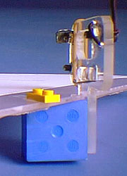 |
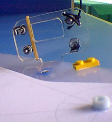
After securing the arm mirror assembly, set the arm to 0°00' reading and place the frame mirror assembly parallel to the arm mirror. I used a Lego Dupplo block (the large blue piece) to support the frame mirror assembly. This way the right angle between the frame mirror and instruments plane is garanteed. I like to use Lego parts (no, I'm not Lego sponsored) because they are widely available (at least in my house floor), have good dimensional precision and there are all sorts of blocks and devices. |
Make sure both mirror holders are firm, by bonding and securing with screws. Having reached this point, you already have a sextant to take twilight sights. But you still need shades do take Sun sights.
Shades
|
Materials that can be used to make the filter:
|
|
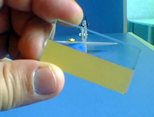
As shade for Sun sights, I used 35 mm dark negative photography film. The negatives were mounted in a slide frame. I used two layers of negatives for the Sun shade. Both slide frames are removable and are attached to the instrument frame using Lego blocks (the yellow one in the pictures above). The thing to watch here is the shade position. The filter surface must be perpendicular to the line connecting the mirror centers. This is to avoid introducing a refraction error. Don't make the same mistake I did, letting the shade support interfere with the arm at large angles. The arm must go at least up to 90° (for the octant). |
|
No eyepiece ?
I was looking for a good 2x or 3x small telescope that I could use as an eyepiece for my sextant. I played with small toy telescopes, but results were poor. In the end, I decided to use no eyepiece. This actually gives a lot of freedom handling the sextant.
When taking a sight, remember to hold the instrument so that your eye is on a plane parallel to the instrument's and containing the fixed mirror silver-glass division. This is easy to find: turn the instrument up until you face the fixed mirror. In this position, you should see half of your eye in the silvered part of the mirror. Move it sideways until you see it. Then carefully turn the instrument back to observation position.
Trimming the mirrors
|
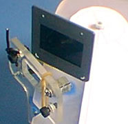
Trimming this octant is no different then any other sextant. First trim the arm mirror adjustment screw. The arm mirror must be perpendicular to the arm/frame plane. This may be checked by looking at the index scale reflected in the arm mirror. The reflected index must be perfectly aligned with the index part you see directly (green arrow on the right). |
 |
Then trim the frame mirror. This is a little trickier, because two screws have to be trimmed simultaneously. Set the arm to 0°00' and point the instrument to a far object (like a star or boat far away). Then trim the two screws until the object remains a single image while you swing and rock about the instrument axis.
- - - - - - - - - - - - - - -
|
|
As future improvements, I would change to a better shade positioning system, add a handle and a case (I'm currently using a cardboard box). The case is probably the most important of the three, for the sextant - like a violin - is not be left hanging around if it is to last long. There are many materials, design ideas and garage junk devices that can used to build a Sextant. If you build such an instrument - using these ideas or not - I would like to hear about it. I would also be happy to show other design solutions here. A sextant is a fun thing to build and getting a precise reading from your own instrument is great.
- - - - - x- - - - |
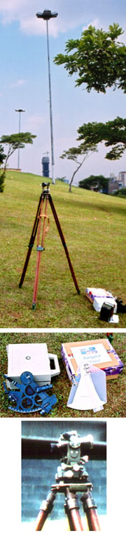 |
I did some tests comparing the same vertical angles, measured by 3 different instruments:
The theodolite (a survey instrument) is presumably more precise than the sextants and was used as a benchmark. Sextant angles were corrected for index error. I measured 4 vertical objects, obtaining the following results:
|
||||||||||||||||||||||||||||||
Bibliography
| >> "The American Practical
Navigator " by Nathaniel Bowditch ISBN 0781220211 - 1200 pages |
|
||
change history:
1. (jun/02) - Added text about inkjet printed
scale problem with water spray.
2. (oct/02) - Added a arm axis screw diagram
3. (nov/02) - Added sextant test results and note about laser print
transfer.
4. (fev/04) - Added note about mirror refraction
5. (dec/15) - Fixed a broken link
©Copr 92-2012 Omar F. Reis - All rights reserved